Executive brief
1. Reliability first
Install a practical generator backup path before hurricane season.
2. Measure before buying
Use service, generator and HVAC submeters to replace assumptions with real load profiles.
3. Reduce the load
Compare Manual J/S, commissioning, duct work and envelope improvements against added battery and solar cost.
4. Buy the durable system
Size GridBOSS, FlexBOSS21 and battery cabinets after the house has been measured and improved.
Existing conditions and confirmed equipment
| Main panel | Square D QO, 30-space cover. Exact load-center catalog number and series remain unconfirmed. |
|---|---|
| Outdoor unit | Bryant 215BNA036-A, 208/230 V, compressor RLA 16.7 A, LRA 79 A, MCA 22.1 A, maximum breaker 35 A. |
| Air handler | FX4DNF037, 208/230 V, ½ HP blower, 4.1 A FLA, no electric heat kit listed. |
| Existing transfer switch | Connecticut Electric EmerGen 6-5000; useful history, but not the preferred long-term architecture. |
| Usage observations | About 60–80 kWh/day occupied in hot weather; about 35–40 kWh/day while away at a 78°F setpoint. |
Unknowns that matter
- Exact QO panel catalog number, series and OEM interlock compatibility.
- True 1-minute and 15-minute whole-house peak demand.
- Overnight kWh from sunset to sunrise.
- HVAC share of daily and nighttime energy.
- Duct leakage, infiltration and room-by-room design cooling load.
- Actual propane consumption per generated kWh.
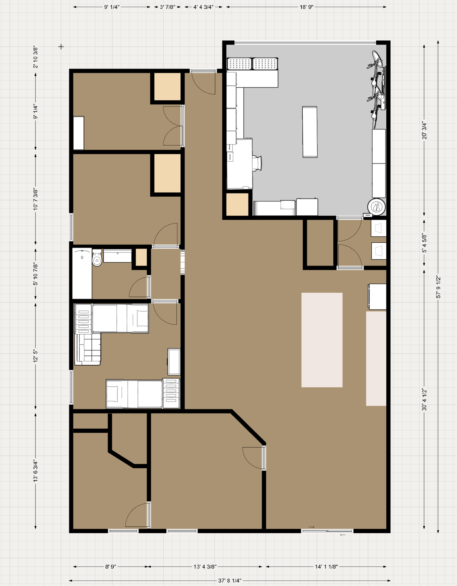
Conceptual site and floorplan overlay
The underlying floorplan is owner-supplied. Markers and routes are conceptual—not surveyed or permit-ready. The proposed generator route reflects the plan to place the generator at the rear and bring the feeder through the attic to the garage electrical zone.
Phase 1 — immediate hurricane backup and instrumentation
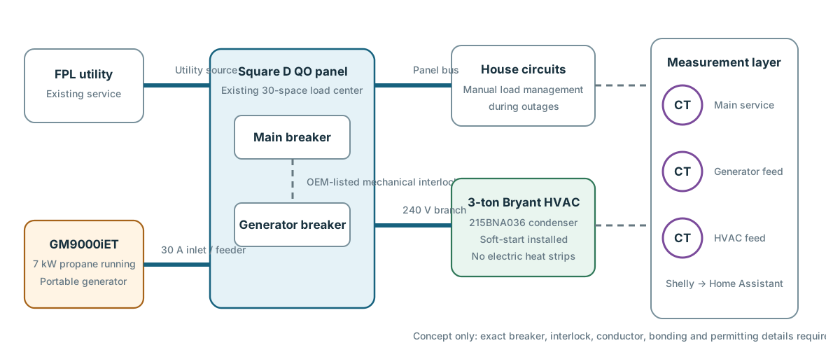
Backup power
- GM9000iET generator candidate.
- Outdoor 120/240 V inlet and long feeder to garage.
- OEM-listed QO interlock after exact panel identification.
- Manual outage load management.
HVAC readiness
- Install a correctly selected soft-start.
- Record pre/post starting current if available.
- Verify blower, refrigerant charge, airflow and static pressure.
- Do not assume reduced inrush changes MCA or branch-circuit requirements.
Measurement
- Main service: both 120 V legs.
- Generator feeder: both legs.
- HVAC: condenser or coordinated HVAC total.
- Home Assistant history plus outdoor temperature and thermostat state.
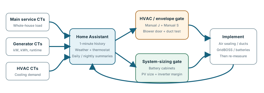
Measurement program — the evidence for Phase 2
| Dataset | Minimum collection | Useful resolution | Decision unlocked |
|---|---|---|---|
| Main service power and energy | 30–60 hot-weather days; repeat after improvements | 1-minute power, daily and nighttime kWh | Battery energy, inverter headroom, base-load audit |
| HVAC power and runtime | Same weather period | 1-minute plus thermostat state; faster capture if available | HVAC share, soft-start performance, comfort strategy |
| Generator power, runtime and propane | Monthly exercise plus every outage | Power, kWh, run hours, fuel added | Charge-current limit, fuel storage and auto-start strategy |
| Indoor/outdoor conditions | Continuous | Outdoor temperature/humidity, indoor setpoint and temperature | Weather normalization and Manual J comparison |
| Post-improvement baseline | At least 2 comparable weeks | Same sensors and setpoints | Verified reduction—not contractor promises |
Suggested Home Assistant entities
sensor.grid_power_totalsensor.grid_energy_dailysensor.generator_power_totalsensor.generator_energy_sessionsensor.hvac_powersensor.hvac_energy_dailysensor.night_energysensor.base_load_rolling_30m
Data-quality checks
- CT direction and phase mapping validated against known loads.
- Energy totals checked against FPL data over several days.
- Generator meter verified under a controlled resistive load.
- Time synchronization and local data retention confirmed.
- Missing-data alerts added before long-term analysis.
Interactive decision lab
Enter measured values when they become available. Defaults are planning placeholders based on current observations. This model is for comparing scenarios, not final engineering.
Current scenario
HVAC and envelope investment versus energy-system size
The second bar uses the editable HVAC share and reduction assumptions from the decision lab. Replace them with measured post-project data.
Measure and commission
Submeter HVAC, verify airflow, static pressure, refrigerant charge, thermostat operation and soft-start performance.
Calculate, do not guess
Obtain room-by-room ACCA Manual J loads and use Manual S for replacement equipment selection. Manual J is a peak-load calculation—not an annual energy forecast.
Test the building
Blower-door and duct-leakage tests identify infiltration and attic-duct losses. Air seal before adding insulation.
Re-measure, then buy batteries
Use comparable weather and setpoints to quantify the actual reduction before final cabinet and PV selection.
| Investment | What it can change | How to judge it | Effect on backup system |
|---|---|---|---|
| Manual J / Manual S consulting | Correct design load and replacement equipment size | Room-by-room report, inputs documented, equipment selected from actual performance data | May avoid oversizing and reduce startup/running demand |
| Blower-door and duct testing | Quantifies infiltration and duct loss | Before/after test results | Can reduce daily and nighttime kWh, shrinking batteries and PV |
| Attic air sealing and insulation | Reduces ceiling heat gain and uncontrolled air movement | Scope tied to test findings; re-measure energy | Reduces stored-energy requirement every outage day |
| Duct repair and airflow correction | Improves delivered cooling and equipment efficiency | Leakage, static pressure, airflow and room comfort | Reduces generator runtime and battery cycling |
| Additional battery cabinet | Adds stored energy only | Usable kWh and outage objective | Improves runtime but does not reduce daily load |
| Larger solar array | Adds daytime production | Roof, shading, MPPT and seasonal production model | Reduces daytime battery draw and generator recharge |
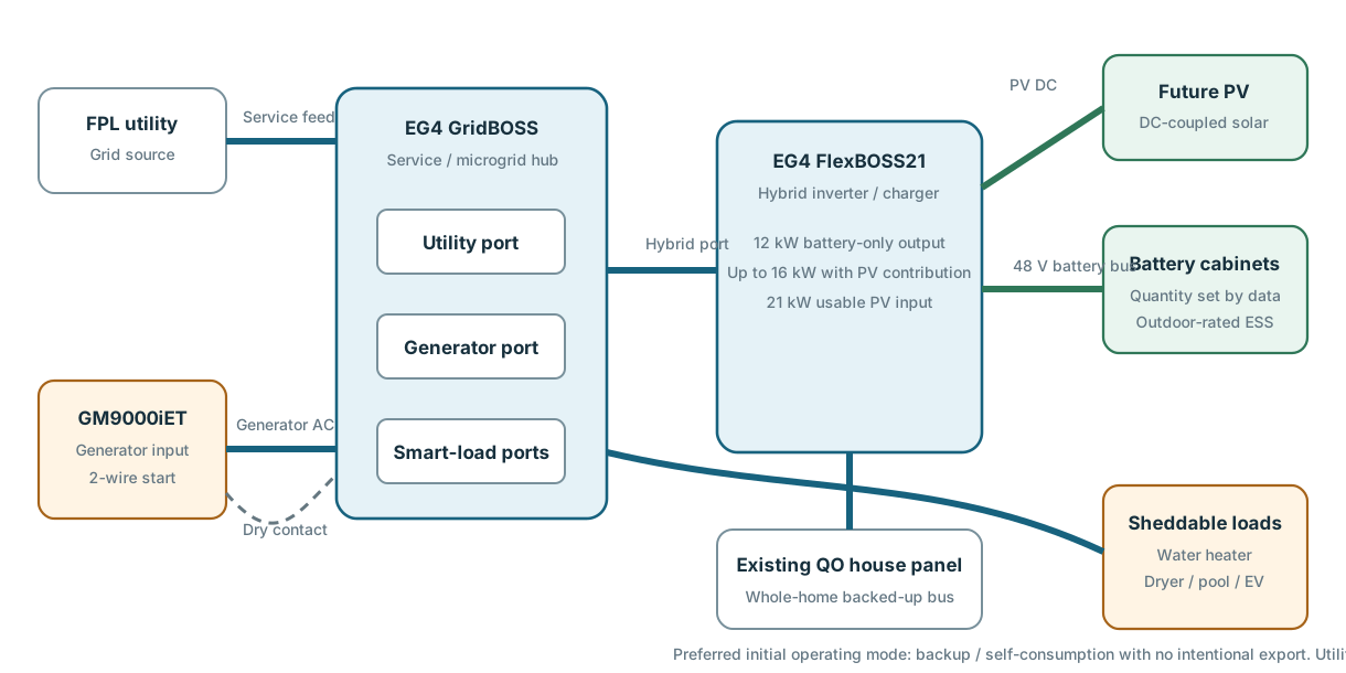
Phase 2 — EG4 whole-home backup and self-consumption
Backup / no intentional export
Grid supports loads and charging; batteries and generator provide outage resilience. Solar can be added later with export disabled or limited if supported and approved.
Self-consumption / zero export
Solar and batteries reduce grid purchases without intentionally sending power to the utility. Utility and AHJ requirements still need confirmation.
Grid export
Net metering or export can be evaluated later. Deferring it avoids letting utility-credit assumptions drive the initial resilience design.
Likely data-driven scenarios and decision points
Scenario A — modest overnight load
Night energy is roughly 12–18 kWh, peak demand stays under about 9 kW, and HVAC starts cleanly.
Response:One FlexBOSS21 and a moderate battery bank may be enough. Generator recharges after extended cloud or multi-night outages.
Scenario B — large overnight cooling demand
Night energy is 25 kWh or more and HVAC exceeds half of total energy.
Response:Commission Manual J/S, blower-door and duct testing before purchasing a third or fourth cabinet.
Scenario C — peak demand near 12 kW
Routine coincident loads approach the FlexBOSS21 battery-only output rating.
Response:Automatically shed water heating, dryer, pool and EV loads; stage compressor and generator charging before considering a second inverter.
Scenario D — high base load
Overnight/base demand remains above about 1 kW even when HVAC is off.
Response:Identify water heating, pool pumps, refrigeration and always-on equipment before adding storage.
Scenario E — generator runs too long
Measured battery recharge takes many hours or the generator stays near maximum continuous output.
Response:Reduce AC charge current, shed house loads while charging, adjust battery reserve, or reconsider generator/battery balance.
Scenario F — improvements outperform estimates
Air sealing, ducts and HVAC work materially reduce hot-weather nighttime energy.
Response:Re-run the sizing model and avoid buying cabinets or PV capacity no longer needed.
Implementation roadmap and gates
Identify and permit
Confirm panel catalog number/series, approved interlock, inlet location, feeder route, grounding/bonding approach and local permit scope.
Install Phase 1
Generator inlet/interlock, soft-start, monitoring hardware, Home Assistant entities and safe generator operating procedure.
Collect hot-weather baseline
30–60 days with stable sensors; include occupied, overnight, away and generator-test periods.
HVAC and envelope decision
When HVAC share or nighttime energy is high, purchase analysis and diagnostic work before storage hardware.
Re-measure and freeze Phase 2 requirements
Set inverter count, battery cabinet count, smart-load plan, generator charge limit and preliminary PV target.
Engineer and install EG4 system
Produce permit-ready one-line and site plan using current hardware-specific manuals, listings and service architecture.
Add solar after commissioning
Size strings from roof/shading and MPPT requirements; choose backup-only, zero-export or approved export mode.
Sources, facts and assumptions
Official references
- EG4 GridBOSS product page — 200 A service architecture and smart-load ports.
- GridBOSS hardware-specific user manual.
- EG4 FlexBOSS21 product page — 12 kW battery-only, up to 16 kW with PV contribution, 21 kW usable PV input.
- FlexBOSS21 specification sheet.
- Shelly 3EM-63 Gen3 documentation — three-channel metering, local protocols and data logging.
- ACCA Manual J residential load calculation.
- ACCA approved software directory.
Owner-supplied project facts
Floorplan, equipment nameplates, current usage observations, generator candidate/rating, desired rear generator location, garage equipment concept, and future outdoor battery preference were supplied in the project discussion.
Planning assumptions
Calculator defaults—including cabinet size, installed cost per kWh, peak-sun hours, reserve and expected HVAC reduction—are editable placeholders. They are not quotations, production guarantees or final equipment sizing.